|
 urrent fixed bed reactor models have been based
on fairly radical simplifying assumptions driven by the complex structure of
random packed tubes. However, even the most advanced models today cannot quantitatively predict reactor behavior if
independently-determined kinetics and transport parameters are used. The effects of tube and catalyst pellet design changes are
lost by the use of effective transport parameters and simplified models. There is a consensus among reaction engineers that the entire field has
neglected the role of fluid flow in reactor modeling. Specifically for fixed beds, what is needed is a better understanding of fluid flow
through arrays of realistic catalyst particle shapes, with special attention to the problematical wall region. The presence of the tube wall
causes changes in bed structure, flow patterns, transport rates and the amount of catalyst per unit volume, and is usually the location of
the limiting heat transfer resistance. urrent fixed bed reactor models have been based
on fairly radical simplifying assumptions driven by the complex structure of
random packed tubes. However, even the most advanced models today cannot quantitatively predict reactor behavior if
independently-determined kinetics and transport parameters are used. The effects of tube and catalyst pellet design changes are
lost by the use of effective transport parameters and simplified models. There is a consensus among reaction engineers that the entire field has
neglected the role of fluid flow in reactor modeling. Specifically for fixed beds, what is needed is a better understanding of fluid flow
through arrays of realistic catalyst particle shapes, with special attention to the problematical wall region. The presence of the tube wall
causes changes in bed structure, flow patterns, transport rates and the amount of catalyst per unit volume, and is usually the location of
the limiting heat transfer resistance.
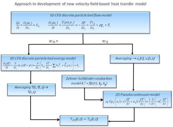 We have proposed a new approach to modeling radial heat transfer in fixed beds. We wanted to discard the use of effective conduction to
represent transport by convective motion of the fluid, which is a purely fluid mechanical phenomenon. A second motivation was to improve
the prediction of temperature profiles and heat fluxes at the reactor tube wall by incorporating the physical phenomena that cause the extra
resistance to heat transfer near the tube wall directly into the model. The strategy for this development is illustrated, along with some
of the main equations. We first had to develop 3D CFD discrete particle models for the detailed flow through a catalyst packing, to provide
the detailed flow fields that give the convective transport. The velocity and pressure fields then had to be incorporated into a 3D energy
balance to give a 3D temperature field. This was then to be averaged to provide a 2D temperature field T(r,z) which was the target of our
new 2D pseudocontinuum model. For this new model, the 3D velocity fields from the CFD model simulations had to be averaged to extract the
essential 2D information to be supplied to the pseudocontinuum model. Some preliminary work suggested that we would need vz(r) and vr(r,z).
In addition, we used the well-established Zehner-Schlünder formula for conduction heat transfer in a stagnant bed to represent the conductive
contribution kr0(r) to the overall heat flux, but it was necessary to verify that it would apply on a point-by-point basis. These contributions
were included in the pseudocontinuum model, which was solved by finite element methods as embodied in the COMSOL multiphysics package. The
resulting pseudocontinuum model 2D temperature fields were then compared against the 2D temperature fields obtained by directly averaging the
3D CFD results.
We have proposed a new approach to modeling radial heat transfer in fixed beds. We wanted to discard the use of effective conduction to
represent transport by convective motion of the fluid, which is a purely fluid mechanical phenomenon. A second motivation was to improve
the prediction of temperature profiles and heat fluxes at the reactor tube wall by incorporating the physical phenomena that cause the extra
resistance to heat transfer near the tube wall directly into the model. The strategy for this development is illustrated, along with some
of the main equations. We first had to develop 3D CFD discrete particle models for the detailed flow through a catalyst packing, to provide
the detailed flow fields that give the convective transport. The velocity and pressure fields then had to be incorporated into a 3D energy
balance to give a 3D temperature field. This was then to be averaged to provide a 2D temperature field T(r,z) which was the target of our
new 2D pseudocontinuum model. For this new model, the 3D velocity fields from the CFD model simulations had to be averaged to extract the
essential 2D information to be supplied to the pseudocontinuum model. Some preliminary work suggested that we would need vz(r) and vr(r,z).
In addition, we used the well-established Zehner-Schlünder formula for conduction heat transfer in a stagnant bed to represent the conductive
contribution kr0(r) to the overall heat flux, but it was necessary to verify that it would apply on a point-by-point basis. These contributions
were included in the pseudocontinuum model, which was solved by finite element methods as embodied in the COMSOL multiphysics package. The
resulting pseudocontinuum model 2D temperature fields were then compared against the 2D temperature fields obtained by directly averaging the
3D CFD results.
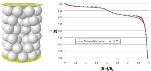 For the conduction mode of heat transfer, we carried out an evaluation of whether temperature profiles and wall heat fluxes in an annular bed
can be accurately represented with a one-dimensional thermal model based on the most successful formula for stagnant bed conductivity, the
Zehner-Schlünder cell model. In this approach, the radial stagnant thermal conductivity is a function of the local bed voidage, ε(r). We
constructed a 3D CFD model consisting of a tube containing a modified bed of 72 particles (6 layers of 12 particles, at N = 4) with a thin
center tube running axially down the center (see picture). The tube wall was held at 700 K and the inner tube at 300 K, with symmetry conditions
on top and bottom, to provide a purely radial temperature gradient across the particles and interstitial gas. The CFD model was solved, the
solution verified by mesh refinement, and temperature radial profiles extracted. A one-dimensional pseudohomogeneous continuum model was then
constructed using the finite element package COMSOL Multiphysics with the same boundary conditions. This was solved by supplying the CFD-derived
voidage values to the program, which interpolated them and used the Zehner-Schlünder formula for kr0(r). Temperature profiles
were calculated and used for comparison to the CFD results. In the graph, we show a comparison of the CFD and pseudocontinuum temperature profiles,
which were in very good agreement. For further details, see the published article
[Dixon, A.G., Gurnon, A.K., Nijemeisland, M., and Stitt, E.H., 2013].
For the conduction mode of heat transfer, we carried out an evaluation of whether temperature profiles and wall heat fluxes in an annular bed
can be accurately represented with a one-dimensional thermal model based on the most successful formula for stagnant bed conductivity, the
Zehner-Schlünder cell model. In this approach, the radial stagnant thermal conductivity is a function of the local bed voidage, ε(r). We
constructed a 3D CFD model consisting of a tube containing a modified bed of 72 particles (6 layers of 12 particles, at N = 4) with a thin
center tube running axially down the center (see picture). The tube wall was held at 700 K and the inner tube at 300 K, with symmetry conditions
on top and bottom, to provide a purely radial temperature gradient across the particles and interstitial gas. The CFD model was solved, the
solution verified by mesh refinement, and temperature radial profiles extracted. A one-dimensional pseudohomogeneous continuum model was then
constructed using the finite element package COMSOL Multiphysics with the same boundary conditions. This was solved by supplying the CFD-derived
voidage values to the program, which interpolated them and used the Zehner-Schlünder formula for kr0(r). Temperature profiles
were calculated and used for comparison to the CFD results. In the graph, we show a comparison of the CFD and pseudocontinuum temperature profiles,
which were in very good agreement. For further details, see the published article
[Dixon, A.G., Gurnon, A.K., Nijemeisland, M., and Stitt, E.H., 2013].
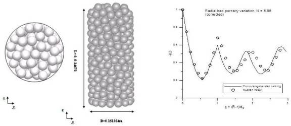 CFD simulations of full beds of particles play a major role in this research. We have studied a range of tube-to-particle diameter ratios (N) for
sphere-packed beds. To do this, we adapted a published “soft-sphere” algorithm (Salvat et al., Catalysis Today, 107-108 (2005) 513-519) which
produces sphere packs with lower voidage than the usual “drop-and-roll” packing algorithm, by allowing a small degree of interpenetration between
the particles. The results are usually in closer agreement with published experimental data than previous work. We found that the random
allocation of spheres in this collective rearrangement type of algorithm gave some unrealistic sphere packings at the bottom layers of the bed,
for low N. We therefore combined the algorithm with an initial position algorithm by Mueller (Powder Technology, 92 (1997) 179-183) to more
realistically locate the wall layer of spheres at the tube bottom. This solved the problem, and we have generated a range of sphere packs. The
N = 5.96 model had 400 spheres and was 0.347 m long and is shown in the picture. Validation of the computer-generated structures has been
conducted by comparison of the radial voidage profile to literature data as shown in the graph for N = 5.96, and also for the other values of
N = 3.96 and 7.99 that were used in this work.
CFD simulations of full beds of particles play a major role in this research. We have studied a range of tube-to-particle diameter ratios (N) for
sphere-packed beds. To do this, we adapted a published “soft-sphere” algorithm (Salvat et al., Catalysis Today, 107-108 (2005) 513-519) which
produces sphere packs with lower voidage than the usual “drop-and-roll” packing algorithm, by allowing a small degree of interpenetration between
the particles. The results are usually in closer agreement with published experimental data than previous work. We found that the random
allocation of spheres in this collective rearrangement type of algorithm gave some unrealistic sphere packings at the bottom layers of the bed,
for low N. We therefore combined the algorithm with an initial position algorithm by Mueller (Powder Technology, 92 (1997) 179-183) to more
realistically locate the wall layer of spheres at the tube bottom. This solved the problem, and we have generated a range of sphere packs. The
N = 5.96 model had 400 spheres and was 0.347 m long and is shown in the picture. Validation of the computer-generated structures has been
conducted by comparison of the radial voidage profile to literature data as shown in the graph for N = 5.96, and also for the other values of
N = 3.96 and 7.99 that were used in this work.
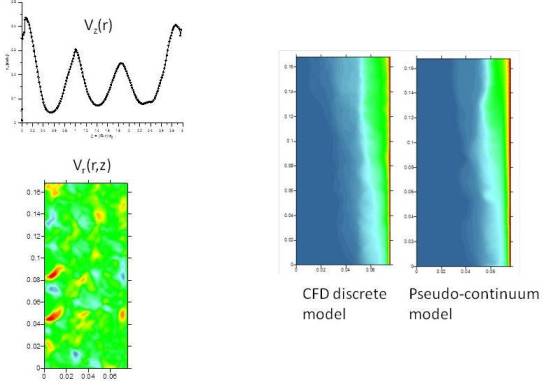 We have carried out 3D CFD simulations to obtain velocity and temperature fields in full beds of spheres for three cases, N = 3.96, N = 5.96 and N =
7.99. The mesh used boundary layer prism cells at outside particle surfaces and at the tube walls, with tetrahedral cells in the main fluid
volume. The N = 5.96 total mesh size was 15.579 million cells, as an example. Simulations were run over a range of flow rates to give Re in the
range 80 – 2000. To simulate the 2D pseudo-continuum energy equation with COMSOL for the low-N fixed bed columns the axial velocity vz(r) and radial
velocity vr(z,r) were extracted from the discrete particle model in CFD to be used in the pseudocontinuum model to represent convection heat transfer. Examples are shown
here for N = 5.96 and Re = 950. The conduction heat transfer was represented by the Zehner-Schlünder model based on the fluid and solid thermal
conductivity and porosity of the bed. The void fraction and axial velocity were extracted from averaging of different cylindrical planes in the
radial direction inside the fixed bed. The 2D model was run for conditions corresponding to the CFD runs and comparisons made between them,
to test the new pseudo-continuum model. Sample results shown here for Re = 950 show excellent agreement for the temperature fields, confirming that
fixed bed heat transfer can be modeled using velocity components to represent the convective contribution.
We have carried out 3D CFD simulations to obtain velocity and temperature fields in full beds of spheres for three cases, N = 3.96, N = 5.96 and N =
7.99. The mesh used boundary layer prism cells at outside particle surfaces and at the tube walls, with tetrahedral cells in the main fluid
volume. The N = 5.96 total mesh size was 15.579 million cells, as an example. Simulations were run over a range of flow rates to give Re in the
range 80 – 2000. To simulate the 2D pseudo-continuum energy equation with COMSOL for the low-N fixed bed columns the axial velocity vz(r) and radial
velocity vr(z,r) were extracted from the discrete particle model in CFD to be used in the pseudocontinuum model to represent convection heat transfer. Examples are shown
here for N = 5.96 and Re = 950. The conduction heat transfer was represented by the Zehner-Schlünder model based on the fluid and solid thermal
conductivity and porosity of the bed. The void fraction and axial velocity were extracted from averaging of different cylindrical planes in the
radial direction inside the fixed bed. The 2D model was run for conditions corresponding to the CFD runs and comparisons made between them,
to test the new pseudo-continuum model. Sample results shown here for Re = 950 show excellent agreement for the temperature fields, confirming that
fixed bed heat transfer can be modeled using velocity components to represent the convective contribution.
|